
{{product.productLabel}} {{product.model}}
{{#if product.featureValues}}{{product.productPrice.formattedPrice}} {{#if product.productPrice.priceType === "PRICE_RANGE" }} - {{product.productPrice.formattedPriceMax}} {{/if}}
{{#each product.specData:i}}
{{name}}: {{value}}
{{#i!=(product.specData.length-1)}}
{{/end}}
{{/each}}
{{{product.idpText}}}
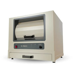
... The DT-230SR is manufactured in stainless steel and especially suited for use onboard ships and offshore installations. The compactor is delivered with a wheeled C-200 container for easy and effective waste logistics. The modular design of the DT-230SR ...
DELITEK
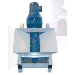
We do also manufacture customized shredders and “special-shredders” for “special-purposes”. Good examples are shredders suitable for shell-fish or fish-farming industries. Please contact us for relevant discussions in case our standard shredder range ...
DELITEK
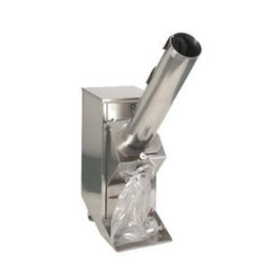
The DT-190LCG glass crusher is manufactured in stainless steel and especially suited for use onboard ships and offshore installations. Especially suited for crushing glass bottles, jars and similar glass materials. The compactor is delivered with a 190L ...
DELITEK

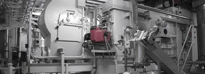
... THE CONVERTER NV SERIES IS INSTALLED DIRECTLY ON BOARD. The solution is a modular, plug and play installation, which is easy to operate. It removes the need to refrigerate waste, because it can be treated right where it is created. One Converter can ...

... THE CONVERTER NV SERIES IS INSTALLED DIRECTLY ON BOARD. The solution is a modular, plug and play installation, which is easy to operate. It removes the need to refrigerate waste, because it can be treated right where it is created. One Converter can ...

... THE CONVERTER NV SERIES IS INSTALLED DIRECTLY ON BOARD. The solution is a modular, plug and play installation, which is easy to operate. It removes the need to refrigerate waste, because it can be treated right where it is created. One Converter can ...
... – Advanced equipment with proven MBR technology MARTIN Systems GmbH is an internationally active company in the field of wastewater treatment. We offer complete on-board systems for maritime applications, including: Flotation systems for the treatment ...
Martin Membrane
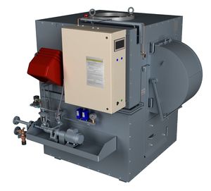
... Marine Incinerator The purpose of a shipboard incinerator is to get rid of solid and/or sludge waste generated on board as an environmentally friendly approach, whereas complying with the latest IMO regulations. In that sense, Detegasa’s Marine Incinerator ...

... This is a cost-effective and single chambered baler unit designed for cardboard or plastic. The waste is placed in the loading chamber at the front and is then compressed by a single ram. When enough material exists in the chamber to form a bale the ...
Loipart AB
The incinerator is designed with the very latest technology in multi-chamber, semi-pyrolysis with flue gas emissions within IMO MARPOL regulations. The incinerators are also capable of meeting EU regulations, which is in accordance with the future general ...
Scanship Environmental as
Our pumped waste systems use a process of homogenisation to convert kitchen scraps and leftovers into a liquid biomass before it even leaves the infeed station. The biomass is then pumped through a sealed system of plastic piping into a storage tank. ...
MEIKO Maschinenbau
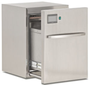
... Are you looking for containers for separate waste collection? Do you have little space and don't know where to put them? Do you want to receive a reward from separate waste collection? Choose the Ginkgo electric bin The only patented technology ...
We manage mixed or recyclable waste in a way that is safe, convenient, environmentally friendly and energy efficient, reducing the volume and space through compaction and shredding.
Ludwig Elkuch AG
... Since 1980, Enviro-Pak® compactors have been focused on 3 main design principles: Simplicity, Safety, and Reliability. Our Model 4000 CB compactor improves on that design by totally enclosing the rollback ram carriage and greatly reducing the possiblity ...
OEG Offshore
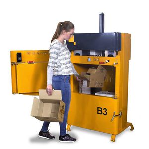
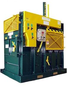
... WASTE COMPACTION AT SEA The Marine B3 baler combines high compaction ratio with a small footprint, it fits easily in tidy and narrow spaces. An automatic full light indicator flashes when a bale is ready and prevents from overloading the chamber. This ...
Bramidan Marine Waste Compactors

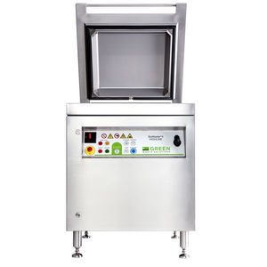
... EcoSwiss EFR devices are high-tech professional devices designed for drying, reducing, sanitizing and enhancing the organic wet fraction of urban waste. WHAT THEY TREAT Devices designed and built to treat all organic waste: meat, fish, bones, bread, ...
EcoSwiss SA

... With its sturdy and compact design and high performance the OG400C is one of our most popular models and an obvious first choice for solving the waste treatment onboard medium-sized vessels. Up to 512 000 kcal/h (596kW) – up to 81 l/h of sludge oil. Extremely ...
TeamTec AS
Kangrim Heavy Industries
The waste packagers of vacompact differ in terms of waste volume, waste collection, loading and device dimensions. Vacompact integrable frontloader 60 litres adapts to the required standard measures, such as the norm of furniture systems. For the integration ...
Vacompact GmbH
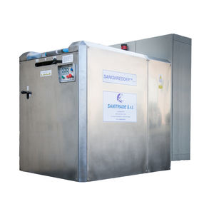
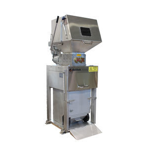
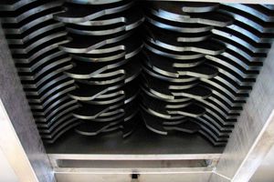
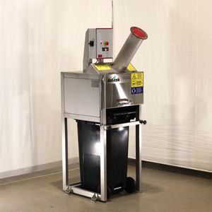
... SANISHREDDER SSH 130 Garbage? Food waste? Cardboard? Plastic? Glass? Metal tins and cans? Sanishredder is what you need Replaces the activity of 4-5 standard machines and stabilize the microbial waste SANISHREDDER comes from the idea to provide a simple ...
Shredders from Mercodor GmbH Sondermaschinenbau KG will help you keep your waste problem in hand. Our shredding systems provide a solution for commercial and industrial enterprises to reduce their waste volume economically and effectively. By choosing ...
Mercodor GmbH Sondermaschinenbau KG
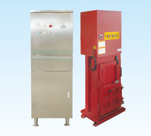
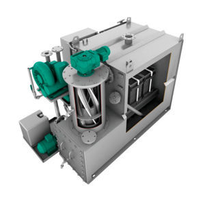
... Use hydraulic drive , important seals , with indepentmeng power structure and electrical systems Push-button control Stand-alone fillinf input , easy to operate , feeding device install safety lock , safe and reliable The foundation form is suitable ...